From
the Workshop
Scroll
down to access required Topic
Quick
Note!


Just
a quick note I have changed my brand of paint as VHT is close to
$20 a tin so have gone to Rust-Oleum @ $12.00 a can from the local
Bunnings Store. There Primer range has a great choice of colours
with White, Red Oxide, Grey & Black which will cover the while
range of Railway items. I have found that it covers very well
& is less prone to run unlike the VHT. Or maybe I have become
more patient!! They also do an extensive range of top coats
which I have used in my White pass Bachmann Coach kits, they came
up a real treat.

New
Mode of Power!
F72
has recenty under gone a bit of an update power wise, had been
thinking of a way to run two trains on an open day at once, with
the only answer seeming to be one battery with one track power I
ordered an onboard unit to convert one loco to Battery. The F was
choosen due to it having its wheels machined to the correct size
& being diecast finish they tended to dirty up pretty quick. A
La runner wagon was choosen due to the fact there was no room in
the loco, so all the batteries & electronics are in the one
place with a couple of wires heading to the motor. It has worked
out rather well as when building future locos I can have them
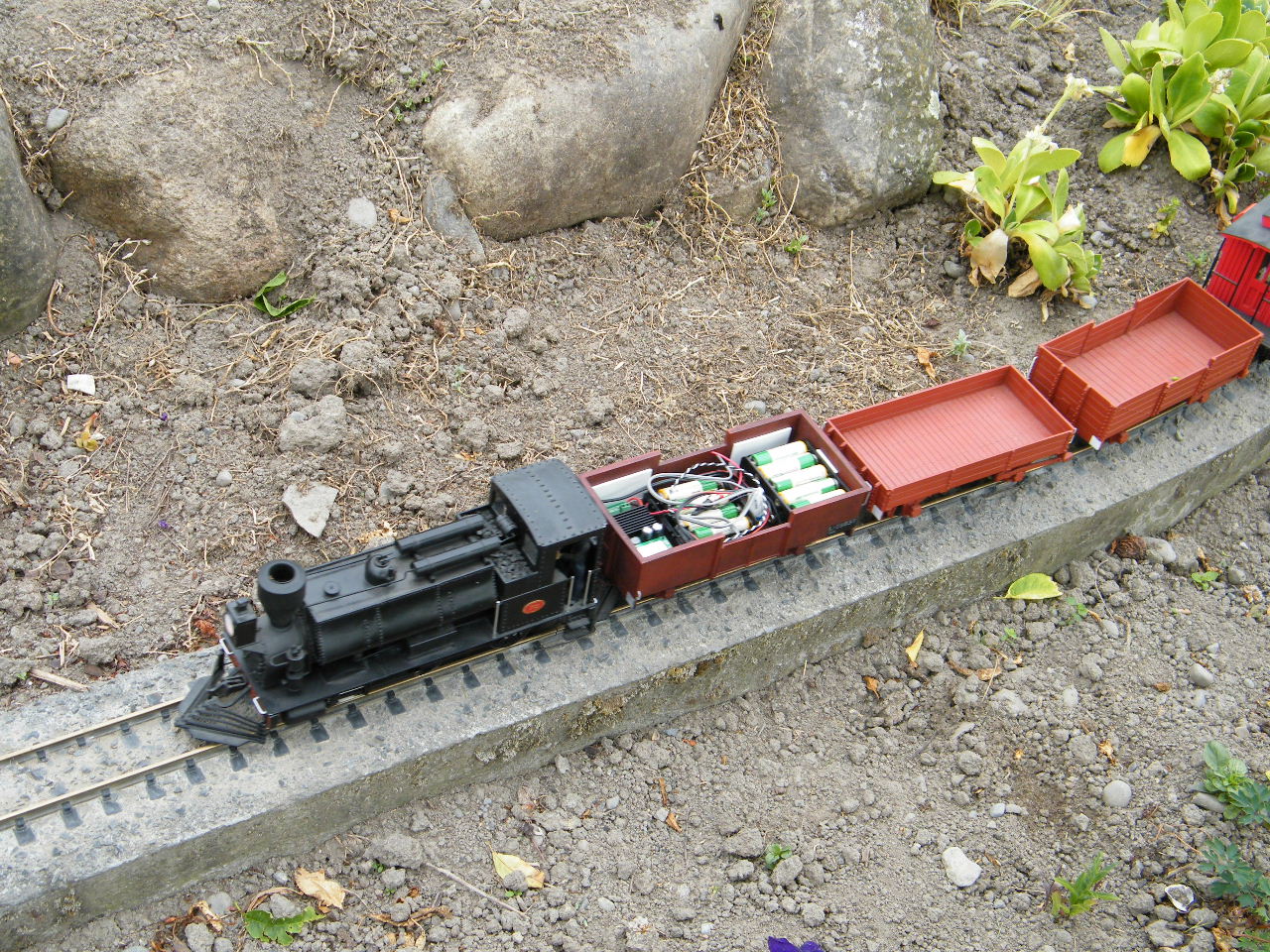
wired up for track or battery & using the same battery wagon. Below;
Shots of the electronics installed in the runner wagon.

To
hide all of the electronic gear I made up an insert of 2mm styrene
with shaped poly-styrene painted black with PE pipe Re-Grind glued
to it. Looks like coal & it's uv resistant!!
Below;
The end result, F72 on a short goods.

Light
Up Wood!
I
thought this was going to be a simple build but it proved other
wise, this was one of those things it had to look right not piled
in a nice tidy heap. The easiest way I found was to cut the
desired length & split with a meat cleaver to get a nice
control. Once all your pieces are cut stretch out some cling film
& place your first layer down, on top of that run a bead of
PVA down the sides 10mm in from the edges. proceed laying the 2nd
layer, I found dropping them from about 50mm high got a good
effect. After about 4 or 5 layers mix up a 50/50 mix PVA &
water with a drop of dish wash & run over your wood pile. Let
it dry for 2 or 3 days & repeat the process until you reach
your desired height. The one pictured is the larger of 2 at the
loco with plans of making one 3 times as long & twice as high.
Forgot to mention is that doing it on the cling film you can peel
it off & place the wood heap any where you want on your
layout.

Simple
Wooden Windows!

Above;
Step One. Make a simple
3 sided jig (top-side-bottom) put your pane spacers in to where
you want them, in the pic it is the 3 pieces of styrene. Cut a top
& bottom, 2 sides & 5 window horrizontal pane pieces. The
pane pieces are a craft stick same size as a match stick. Where
all the joins are drill an over-size hole in the jig so when
gluing the excess goes down the hole with it not sticking to the
jig, it makes getting the frame out alot easier!!! Assemble &
glue into place, clamp the 3 jig sides then push a straight edge
piece of timber up against the 4th side & weight it til it
dries. I left mine over night so I could go onto the next step
while another one was in the frame jig. ( so I got one window
finished in 1 hour each day)

Above;
Step Two. The vertical pane pieces
are all done free hand with what ever spacing required as
pictured, all this was glued on a flat piece of aluminium.
The outside casings are glued onto the frame with a sill glued
onto the bottom. I haven't given any measurements as each set of
windows for certian buildings are all different so what ever the
project there will be a window for it!
Corrugated
Iron/Styrene!
I got a set of
alloy rollers 10 to 15 years ago from a fellow modeller who
was going out of G so got them out & modified
them to take 0.5-0.75mm styrene. I cut the sheet about 3.5
inches wide & about 300mm long so it goes through
the rollers easily, while rolling apply a little heat from
a heat gun/hair dryer to soften the styrene a bit. Once it
passes through once turn it over & pass through
again. Once you have a large corrugated sheet place between
2 flat surfaces & apply some weight to keep flat,
once 10 or 15 minutes have passed you can cut your sheets
to size by cutting down the corrugation to the width
you require then square off the ends as no matter how
careful you are it may come out the rollers with a bit of
an angle. Once cool I have found that it stays true
to its new shape & is more robust then the can option.
But having said that this method is for an indoor building
,but I do have a steel girder bridge that is painted
styrene & has been out side 12 years. This is my
preferred method as I can glue the sheets together &
know that they will stayed glued as well as pinning them. Below
Left; Passing the styrene through the rollers with the heat
gun providing heat. Below Right; Cutting the end of the
sheet square.


Boiler
Washouts & Hand-Rail Stanchions!
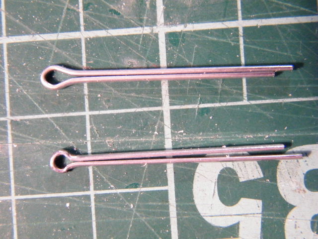

Above
Left; To the top of the picture is a standard small split pin,
now we have to get the eye of the pin to a more rounded shape. The
way I do it is squeezing below the eye with pliers then pushing a
piece of the to be handrail in the eye & crimp again below the
eye with pliers, last but not least tap all arouund with small
hobby hammer to achieve the finished result. Above Right;
Boiler wash-outs are made from pop-rivets, remove the stem of the
rivet then machine (or file) the head as thin as you need it.
drill a hole bigger then the existing hole 3mm deep to form a step
for the false bottom to sit on. Use a hole punch to cut out false
bottom & glue in place, cut a piece of hex or square to glue
on the false bottom in the centre & there you have it a boiler
wash-out!!!
Below;
A close up of the front handrail detail!!

K-Line
Irrigation in 1:24

It
was only a matter of time that I bought my work home with me!!! I
work for R X Plastics which make the K-Line Irrigation system
& is my job to process & make up the orders so thought why
not model them. I started to look around for something the right
size & ended up in Spot Light in Christchurch. I purchased a
bag of 20 wooden beeds now off to the workshop! Below Left;
Had to machine off 4mm top & bottom then machined out the
centre, glued a 1mm styrene bottom on the pod then drilled the
side holes for the pipe to go through. I used black hat elastic
for the pipe as it can sit in any configeration on a display. Below
Right; The finished result, these was on the club layout at
the show with a 4 wheeled motor bike at the front to look like
they were being shifted, surprising how many commented,on them!!


No2
Bridge gets Attention!
The
walk way on No2 bridge has finally done its dash, it was untreated
plywood so has lasted very well, at least 7 or so years! This time
I used black plastic which I cut into strips, I had to pin the
strips as well as glue them for extra strength. I then weathered
them with some brown water based paint to take away the plastic
look!
Below
Left; A before shot of the damage time has done! (not to
mention the new puppy who thinks she is a train)
Below
Right; The finished result, time will tell.


Simple
Electrical Box!
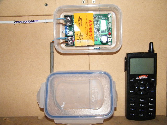
We
recently upgraded our main control system for main line heavy
train running to the new Aristo-Craft Train Engineer which I might
add is fantastic with great control of your trains. We needed a
small electrical box to house the reciever, so down to the
Warehouse we go & bought a self sealing click clack box for a
couple of dollars, job done! Below; A shot of the finished
result up & working.
USA
Trains Turnout Fix-up!
USA
Trains make a fantastic turn-out, AFR has 4 of these in operation
in the shed on the mainline, 2 years ago a screw worked loose so
pulled up 2metres of track either way of it to get access to the
under side & replace the screw. Thinking this was a one off
problem no other precautions were taken.
Nearing
the end of the September Club Day run I noticed the same problem
had occured again this time a different turnout at the oppisite
end of the loop, New Zealand Rail fish plates save the day as I
just needed to slide them back to release the join to lift out the
turnout to access the underside & the screw was replaced.
So
the problem was to stop this happening again, I could not glue
them with anything as it has a jumper wire running to it, so I
came up with the spacer idea.


Above
Left; The 2 red dots are where the screws are positioned, I
thought if I made packers high enough to just touch the head of
the screw it would stop them un-screwing. The packers (Orange
Dots) are made from scrap styrene & all 4 turnouts had
different height packers so do each one seperartely. Above
Right; A side on shot of the packer in place, it is secured
with a good supa-glue & pinned into the base board as well.
In
theory this should work, but if nothing else it has high-lighted a
small problem that can be fixed before installing this great
product from USA Trains.
|
F72
Chassis Re-Build

In May
2010 the Bachmann chassis of F72 finally gave up the ghost
after a running life of ups & downs of reliability. It
was decided to have ago at building our own chassis, this is
a first for the AFR so the methods used could be totally
different & quite basic as I have used bits from scraped
locos & materials that I have obtained from different
sourses ;-)


Above
Left; the chassis is constructed out of 32mmX30mm
aluminium door channel. Above Middle; all the axle
holes, power pick-up holes etc have been drilled & the
bottom runners (the curve pieces) have been cut off. 4mmX4mm
spacers hve been added these were drilled & tapped with
machine screws with the heads filed off. Above Right;
a clear view of the underside with spacers in place.

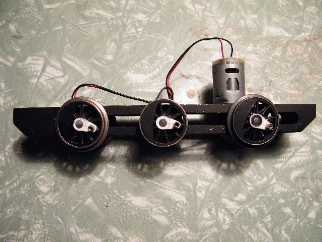

Above
Left; close up of the crank pin, these had to be added
as the wheels were only spoked with-out crank pins. This was
done by filing a slot in the pin & slipping over the
spoke with a collar to hold in place while the glue set.
Above Middle; motor & wiring are all in place. Above
Right; under-neath shot showing the bachmann pick-ups in
place, the bearings used are nylon so will be interesting to
see how the wear!

Above;
F72 on its test run after major work on her chassis, I am
very pleased with the result as this is my first attempt at
chassis work, but time will tell!!
|
|